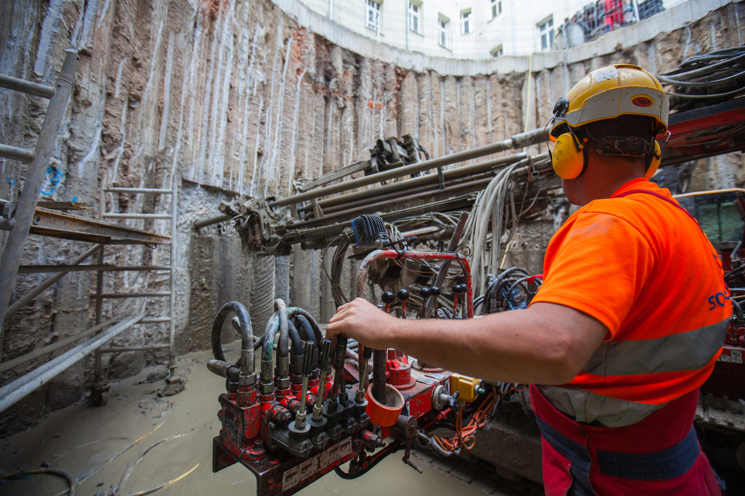
Soletanche Bachy is the world leader in foundations and soil technologies.
Soletanche Bachy is the world leader in foundations and soil technologies.
We offer innovative, high-performance solutions for the deep foundations, underpinning, reinforcement and geotechnical infrastructure of our clients’ structures.
Aware of the environmental impact of its activities, Soletanche Bachy has made strong commitments to reduce its carbon footprint in the long term. In the field, we are also developing solutions to meet the environmental challenges of our customers and their projects:
We build structures with a positive impact
Our technical expertise reduces the environmental impact of projects
Our on-site actions help to protect the environment
At Soletanche Bachy, the future you build is under your feet.
Soletanche Bachy offers you unique opportunities for career development and international mobility. Come and build your career in a company that is committed to developing innovations and environmental solutions for the future.
You can change these settings at any time. However, this can result in some functions no longer being available. For information on deleting the cookies, please consult your browser’s help function.
Learn more about the cookies we use.
With the slider, you can enable or disable different types of cookies:
This website will
This website won't
This website will
Essential: Remember your cookie permission setting
Essential: Allow session cookies
Essential: Gather information you input into a contact forms newsletter and other forms across all pages
Essential: Keep track of what you input in a shopping cart
Essential: Authenticate that you are logged into your user account
Essential: Remember language version you selected
This website won't
Remember your login details
Functionality: Remember social media settings
Functionality: Remember selected region and country
Analytics: Keep track of your visited pages and interaction taken
Analytics: Keep track about your location and region based on your IP number
Analytics: Keep track of the time spent on each page
Analytics: Increase the data quality of the statistics functions
Advertising: Tailor information and advertising to your interests based on e.g. the content you have visited before. (Currently we do not use targeting or targeting cookies)
Advertising: Gather personally identifiable information such as name and location
This website will
Essential: Remember your cookie permission setting
Essential: Allow session cookies
Essential: Gather information you input into a contact forms newsletter and other forms across all pages
Essential: Keep track of what you input in a shopping cart
Essential: Authenticate that you are logged into your user account
Essential: Remember language version you selected
Functionality: Remember social media settings
Functionality: Remember selected region and country
This website won't
Analytics: Keep track of your visited pages and interaction taken
Analytics: Keep track about your location and region based on your IP number
Analytics: Keep track of the time spent on each page
Analytics: Increase the data quality of the statistics functions
Advertising: Tailor information and advertising to your interests based on e.g. the content you have visited before. (Currently we do not use targeting or targeting cookies)
Advertising: Gather personally identifiable information such as name and location
This website will
Essential: Remember your cookie permission setting
Essential: Allow session cookies
Essential: Gather information you input into a contact forms newsletter and other forms across all pages
Essential: Keep track of what you input in a shopping cart
Essential: Authenticate that you are logged into your user account
Essential: Remember language version you selected
Functionality: Remember social media settings
Functionality: Remember selected region and country
Analytics: Keep track of your visited pages and interaction taken
Analytics: Keep track about your location and region based on your IP number
Analytics: Keep track of the time spent on each page
Analytics: Increase the data quality of the statistics functions
This website won't
Advertising: Tailor information and advertising to your interests based on e.g. the content you have visited before. (Currently we do not use targeting or targeting cookies)
Advertising: Gather personally identifiable information such as name and location
This website will
Functionality: Remember social media settings
Functionality: Remember selected region and country
Analytics: Keep track of your visited pages and interaction taken
Analytics: Keep track about your location and region based on your IP number
Analytics: Keep track of the time spent on each page
Analytics: Increase the data quality of the statistics functions
Advertising: Tailor information and advertising to your interests based on e.g. the content you have visited before. (Currently we do not use targeting or targeting cookies)
Advertising: Gather personally identifiable information such as name and location